News
Oct. 2024: M-Cube is transitioning to its next-stage: Supported by an NSF CIRC project, we are developing a new version of M-Cube which is more compact and will be integrated with FR1/FR3 modules to form a muti-band extremely wideband software radio platform.
Sep. 2024: NeuroRadar paper was highlighted in ACM GetMobile and Communications of the ACM Research Highlights.
May 2024: M-Cube software radio/radar was demonstrated at the San Diego 6G Summit, co-hosted by UCSD and Qualcomm.
Nov. 2023: NeuroRadar paper received the Best Paper Award in ACM SenSys’23.
Sep. 2023: M-Cube community QnA repo is online. Please post any questions in the issues. We are aware of one bug the Microtik router is only able to load the codebook to module 0. We are trying to figure out the reason and find out a way to fix it.
Aug. 2023: M-Cube Workshop is held at UC San Diego. The event videos are online: Link to RF front end………… Link to baseband processing.
Apr. 2023: We are constructing the website for the Microtik device. Please refer to M-Cube with Microtik Devices – The M-Cube (M3) Project
June 2022: We gave an in-person demo at MobiSys’22. Glad to meet with the users and receive your feedback. Recently, we did a few updates on this webpage and our codes. We will also keep updating the manual. Please remember to check this page frequently.
Jan. 2022: A low-cost and powerful RFSoC 2×2 Kit (~$2000 for 2 GHz bandwidth 2×2 channels) is available for academic users now. We are developing and testing the FPGA interfaces with M-Cube.
Oct. 2021: 9 research institutions in the US and EU are using M-Cube in their mmWave sensing, communication, and networking projects. 5 other requisition requests are under processing.
Sept. 2021: We are starting a new collaboration project with pSemi to develop a 28 GHz software radio platform, using our RFSoC module as a baseband processing unit.
Sept. 2021: We are developing a new baseband processing unit for M-Cube, based on Xilinx RFSoC. The new baseband will substantially improve the receiver sensitivity (and hence range) for both communication and sensing applications.
Mar. 2021: M-Cube replicas have been delivered to 4 other research teams. We are preparing additional units for multiple other research labs.
Sept. 2020: M-Cube received the Best Paper Award at ACM MobiCom ’20 (2 best papers out of 384 submissions).
Aug. 2020: The First batch of fabrication and assembly is done. We are distributing the units to other research institutions in the form of equipment transfer.
July 2020: COVID-19 delayed the fabrication and assembly of M-Cube by a few months.
Apr. 2020: We are working on fabricating the bridge board sets and assembling the system. Please contact us if you are interested in our system.
Feb. 2020: Camera-ready version of our M-Cube paper is available on http://xyzhang.ucsd.edu/papers/RZhao_MobiCom20_M-Cube.pdf .
Jan. 2020: M-Cube is accepted by ACM MobiCom’20, a top-tier conference in wireless systems and networking.
Overview
M3 is the first mmWave massive MIMO software radio. It provides up to eight 32-element phased arrays, at a cost that is an order of magnitude lower than existing commercial mmWave SDR solutions. Rather than building an expensive custom phased array for research, we design a novel reconfigurable radio architecture, which “hijacks” a commercially-available mmWave radio to allow for arbitrary waveform transmission and real-time phased array reconfiguration.
Open-Source Design Files & Codes
We are providing the code and design files needed to build an M3 radio:
- IF bridge board schematic:

- Real-time phased array controller code, including the FPGA code and Matlab interface
- Matlab interface for USRP, enabling high-speed RF capture (Tested with N310, B210)
- Router setup scripts
- Codebook generation codes
The hardware design is licensed under the Creative Commons Attribution-NonCommercial-ShareAlike 4.0 International License. Contact us for details on commercial use. See the software repositories for details on software licensing.
Notice Before Testing
- The first thing to emphasize is that the hardware is vulnerable, any ESD or cable sudden disconnection while the hardware is operating may result in a broken of the NIC’s IF port. To avoid breaking the devices, do double-check that the interface is down whenever you want to change the connection. A broken NIC port will result in the ‘ifconfig: SIOCSIFFLAGS: Timer expired’ error when initiating the interface. But don’t worry if one IF port is broken, it does not mean the platform is not useful or need to buy a new set. The NIC has in total 8 IF ports and all of them can be used, please check the FAQ section for how to identify and change to another functional IF port.
- Double-check before plugging the Ethernet cable into the router, plugging into the console port may burn the router.
- We strongly recommend first reading our paper M-Cube. It will give you a clear idea of how the system works such as how to can we repurpose the commercial hardware to an SDR, how the phased array is controlled, how to do a calibration and utilize the large phased array, etc.
- We will keep updating this page, please check the FAQ first to find whether it gives the answer. Also, do not hesitate to contact us when you have any questions. We will try our best to give a quick and detailed answer.
System architecture
Supplies of the Airfide hardware described here are limited. We are preparing experimental support for widely-available Mikrotik devices. More details are here.
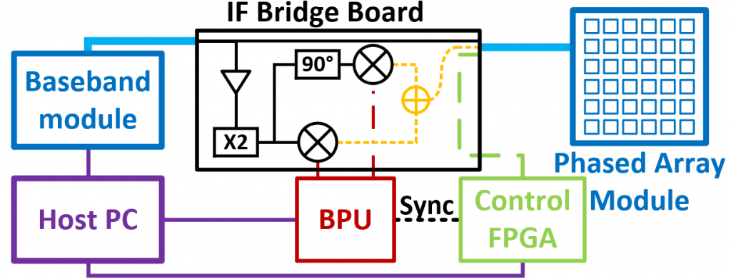
M-Cube’s single-chain architecture is shown in Fig. 2. In our design, the baseband module (BM or 11ad NIC) and phased array module (PM) is a commercial multi-array 802.11ad node. The IF bridge board is a customized PCB. The baseband processing unit (BPU) can be an FPGA or an SDR such as a WARP board or USRP. The control FPGA is a Cmod A7 module with an adapter board. Some offboard connectors are used to connect the modules.
The following documentation describes:
- Instructions for hardware assembly
- System initiation
- BPU configuration
- Control FPGA configuration
Hardware Assembly
The hardware we shipped contains a Sparrow+ router, IF bridge board, programmed control FPGA, and cables to connect these components. Some additional but common hardwares are needed to make the system fully functional. Following is a requirement example for two Mcube nodes with 2 by 2 configuration.
- You will need one Host PC which has RJ45 ethernet port and USB A ports. (Two RJ45 ports or an additional ethernet router might be needed if you want to control the two routers with the same PC at the same time)
- Four (or five if you use an ethernet router) ethernet cables to connect host PC, PoE adapters, and the 60GHz routers.
- One USB A to micro USB cable for connecting the control FPGA with the Host PC.
- Four (heterodyne) or eight (homodyne) SMA cables to connect the bridge boards with the BPUs.
- There are two choices to power the bridge boards:
- 4 USB A to micro USB cables connecting the bridge boards to a power bank or PC USB A ports.
- Using a DC power supply. (Need some soldering, just connect the 5V and GND on the bridge board).
- Dupont wire or similar cable for connecting the trigger port of control FPGA and the BPU. (Needed for synchronization)
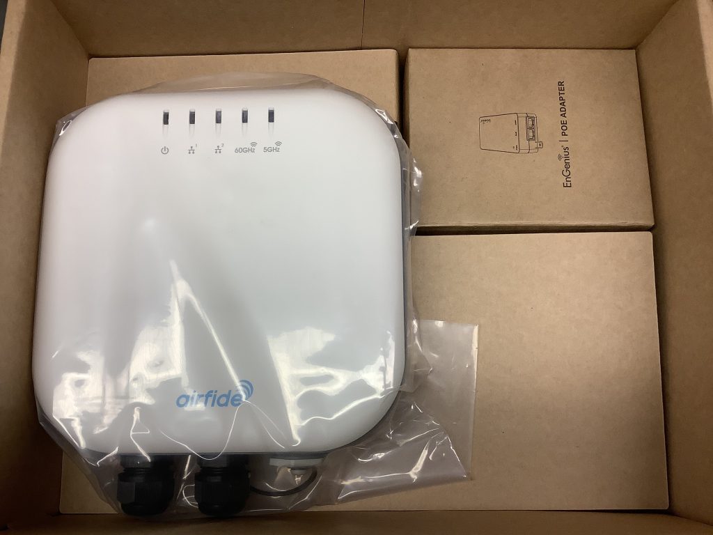
Sparrow+ from Airfide
In the box, there are one router and one PoE adapter. The boxes will be opened for test before shipping. The router’s powering and communicating with the host PC will be through the PoE adapter. Two ethernet cables are needed, one for router – PoE adapter connection and one for PoE adapter – host PC connection.
Since we need to add the bridge board in the RF path. The first step is to take the router board out of the weatherproof case. (We will remove all of the screws during the test and leave them in a bag.)
Fig. 4 is the top view of the router board. The first port needs to be connected to the PoE port of the PoE adapter. The second port can be used for cascade connection, connect this port 2 with port 1 of another router board. (Note that the power from the adapter may not be large enough to support too many routers. We do not recommend doing so.) The console port is a serial port for debugging. (Need an RJ45 to USB adapter or DB9 to RJ45 Console Cable + DB9 to USB adapter) The 4-pin header on the right side also has the same function. (Need USB to UART adapter) If you have forgotten the password or the IP address, you can log in as a super user through a Serial port with a baud rate of 115200.
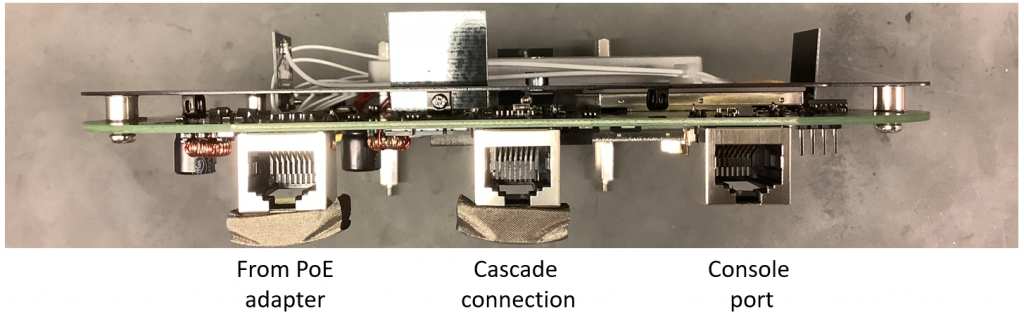
Fig. 5 is the front and rear view of the router board. When the router board is powered through a PoE adapter, the most left LED will first show an amber light during boot loading and then turn to green. The whole initiation takes around one minute. Then you can log in to the router OS through ssh from your host PC. The IP address will be marked and should be 192.168.137.1/24 or 192.168.137.2/24 after our test. The user name is ‘root’ with password ‘123456’. you can change the password after login through ‘passwd’ command. The IP address can be modified by changing the IP address of the bridge interface in the file ‘/etc/config/network’.
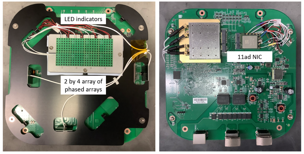
The router has a 2 by 4 array of phased arrays. Each phased array is a 6 by 6 array and has 32 functional antenna elements. (The 4 on the corner are not functional) The 8 phased arrays are connected to the 8 ports of the 11ad NIC. The NIC is also available here. Mikrotik wAP 60Gx3 use the same chipsets and phased arrays but only used 3 modules (module 0, 1, 5). The red and black cable connecting to the phased arrays will provide a 5 V supply. The connector of the power cable seems to be this one (corresponding header).
Another connection of the phased arrays are the white coaxial cables which are connected to the 11ad NIC. These cables are the ones we thoroughly studied in our paper. The coaxial cable has JSC connector from Murata. You can replace the cable if the original one is not long enough or the cable is broken due to too much unplugging. (MXJA01JA5000 is too long and will introduce too much attenuation. Do not buy MXJA01XX2000 since one side of it does not have the connector) (Murata has discontinued the fabrication of the connectors and the cables. If you find any source that can get the JSC connectors and cables, please let us know.) We suggest disassembling the phased arrays from the front panel and taking them to the back side to get more room for bridge board connection.
There are 8 ports on the NIC and the corresponding 8 phased arrays. Identifying the index will be important for the RF module control. Interestingly, Airfide and Qualcomm provide two sets of indexes for them. The index and mapping between NIC and the array of phased arrays provided by Airfide are shown in Fig. 6. They have the index on the metal heat sink. Note that this is just the initial configuration, the index is bound with the IF port of the NIC. You can connect any PM with one IF port and the index will not change.

The Qualcomm index is more useful for module control since the module number in the codebook file and WMI command (rfc module index) are following Qualcomm index. The relationship between the module number in brd file (Qualcomm index), the number in the photo, and the color on the cable is:
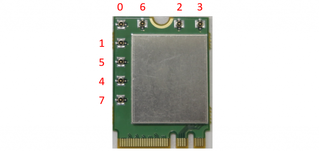
module[0] → 7 → black
module[1] → 4 → none
module[2] → 3 → green
module[3] → 0 → yellow
module[4] → 6 → gray
module[5] → 5 → red
module[6] → 2 → blue
module[7] → 1 → purple
In the following sections, we will follow Qualcomm index when we mention the module number.
Router configuration
Before connecting the bridge board, we suggest first trying the host scripts with the Sparrow+ router alone to get familiar with the commands. Make sure all the coaxial cables between BMs and PMs are connected before powering up the devices. The following steps are needed to be done every time the router is restarted. The host scripts are available here. The main purpose of these scripts is to set up the NIC and phased array to let them ready for the SDR function. The main steps here are i. copy essential files to the router for further NIC configuration; ii. setup a control server and initialize the wireless interface iii. enable rf modules and load codebooks to the phased arrays. Following are the detailed steps:
- Connect the PC ethernet port with the LAN port on the PoE adapter. Connect PoE port on the PoE adapter with the PD port of the router to power up the router. Change the host PC IP address to 192.168.137.XXX/24 subnet. There are three dependencies for the scripts, ‘python2’, ‘sshpass’ and ‘scipy’. We suggest using Ubuntu 18.04. (For 20.04, you will need to install python2 and set up ssh to support the legacy KexAlgorithms.)
- After the LED turn to green, ping 192.168.137.1 and 192.168.137.2. When ping success, login to the router system through SSH. (SSH terminal)
ssh root@192.168.137.1- enter password 123456
- open another terminal and repeat with 192.168.137.2.
- Open another terminal (Script terminal) and cd to the dir of the scripts. Copy the files and initialize the interfaces for two routers.
sh setup_server.sh 1sh setup_server.sh 2- This script setup_server.sh accepts one input, which is the last dotted value of the IP address.
- Note: When the bridge board is connected, there might be an error says ‘ifconfig: SIOCSIFFLAGS: Timer expired’, and the ifconfig result doesn’t show wlan0 during this procedure. This sometimes is caused by an unsuccessful initiation since the spiliting circuits introduce too much attenuation to the control signal from the NIC. To fix the issue, try running the script again or **power down** the router, adjust the bridge board connection and start from step 2 again.
- Switch back to the SSH terminals. Run the following command to start the server.
python /tmp/wil6210_server- You will see the control server running and providing some info. Leave the server running in the terminal and do not close the terminal, it will provide many useful responses when you use the scipts.
- Repeat for the second one.
- Switch back to the script terminals. Enable certain RF modules and load the codebook.
sh ldcb.sh 1sh ldcb.sh 2- This script can accept two inputs, first one is for the IP address. The second one is the RF module to be enabled. Module 0 is 1; module 7 is 128. If you want to enable 0 4 7, the input should be 2^0+2^4+2^7 = 1 + 16 + 128 = 145. The module number is the one mentioned here. The default value is 129 which enable module 0 and 7 corresponding to hardware index 0 and 7 mentioned here.
- There will be some responses in the script terminals and the SSH terminals.
- In the load_codebook.py, it loads the 15 beams codebook saved in 15beam.mat. You need to change these files if you want to load your own codebook.
- Note: During this time, if the server gives an output of
- You can check whether the configuration is success by running readback script.
python read_codebook.py 1 0 0 10- This script accepts 4 inputs. First one is for the IP address. Second is the RF module number to be checked (0 to 7). Third is sector type 0 for RX and 1 for TX. Forth is the sector number, 0 to 127.
- The output should the same with the setup in step 5. By default, the magnitude variable should be all 7.
These procedures give an idea on how to configure the router through the server and scripts we provided. Following we will introduce how to turn it into an SDR.
Bridge board
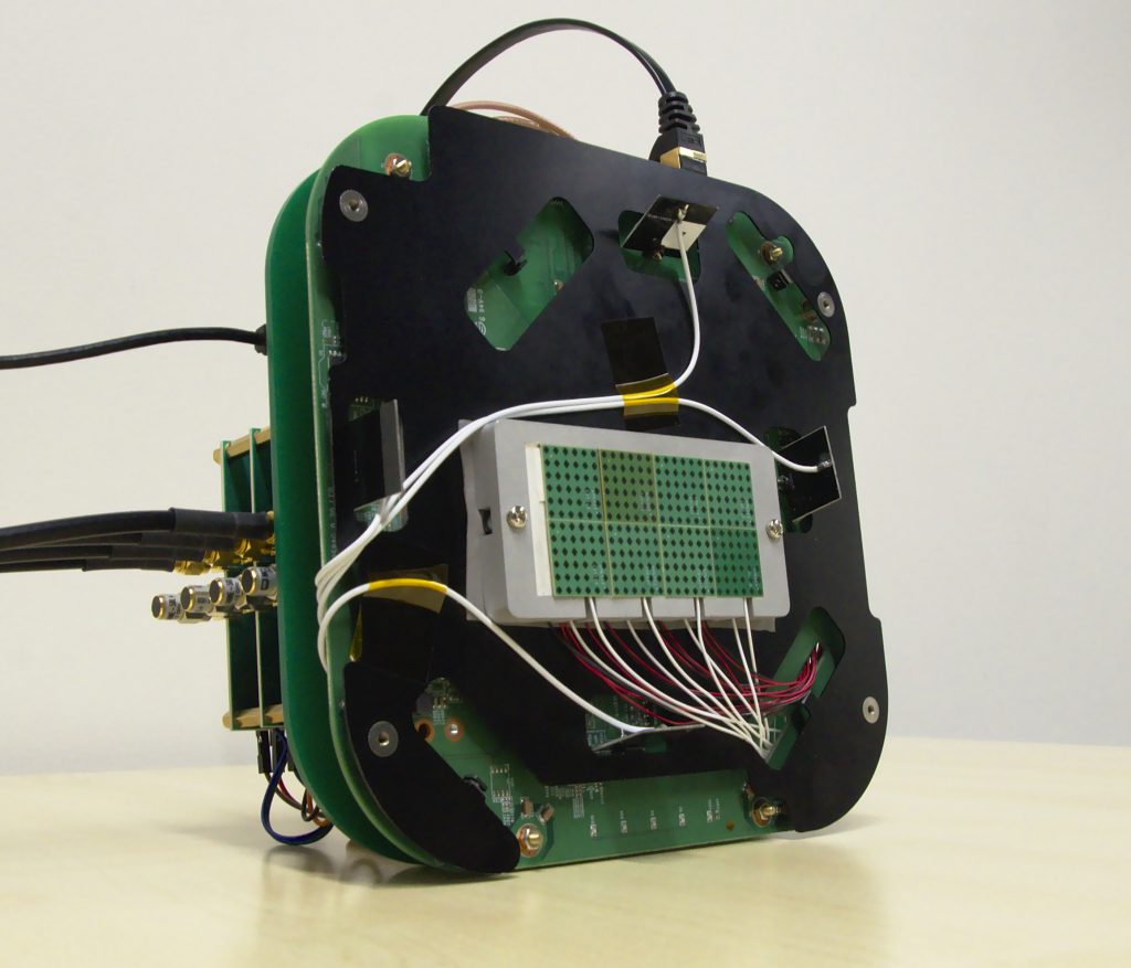
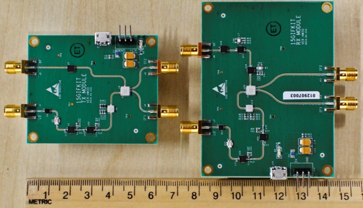
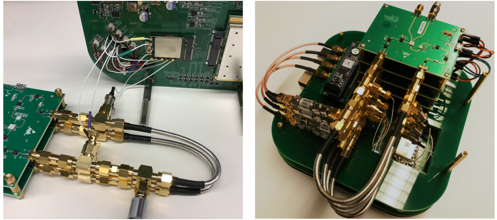
The bridge board is most important component in our platform. It acts as the brige between BPU, BM, control FPGA and PM. Fig. 7 is the photo of TX and RX bridge board modules. These modules needs 5V DC power supply through the header or the micro USB port.
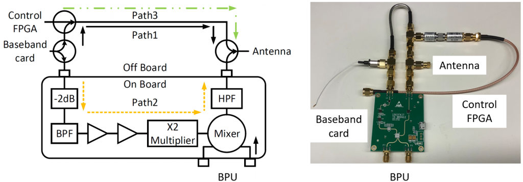
To interface with the baseband module, phased array module, control FPGA and BPU as shown in system diagram, we choose to use off board components for the convenience of debugging and future design flexibility. Fig.8 shows the on/off board connection. All of the components shown in the photo will be provided and pretested. We may take down the cables to baseband card and to control FPGA during shipping. Just assemble them as shown in Fig. 8. Note that the cable to the baseband card is a cable with sma to JSC connectors, you need to connect the JSC connector to the BM.
All together
As shown in Fig. 9, the connection between bridge board and sparrow+ is through coaxial cable. The port connection can be very flexible referring to the mapping. We recommand to use the antenna with index 7 and 0 first since the limited length of the original cable. You can take down the array of phased array off from the front panel for more flexibility. The whole system connection is also shown in Fig.9. (Note, the green plastic supporter is not available right now.)
BPU configuration
The BPU can be two kinds of architecture homodyne and heterodyne as shown in Fig. 10.
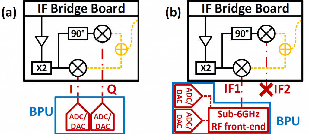
The BPU is not provided but we have tested several widely used setups and provide the reference design.
For homodyne architecture, we have tested:
(i) The FMC150 BPU uses a Virtex-6 LX240T FPGA with an FMC150 ADC/DAC board supporting a 40 Msps I/Q sampling rate. We developed the FPGA bitstream to be compatible with the WARP v3 PC host driver.
(ii) The FMCDAQ2 BPU uses a Xilinx KCU105 development board with an FMCDAQ2 1 Gsps ADC/DAC a Kintex Ultrascale XCKU040 FPGA running the open-source FPGA bitstream developed in Openmili.
For heterodyne architecture, we have tested USRP N210, B210, N310, and WARP board. B210, N310, and WARP board has GPIO output to trigger the beam sweeping of control FPGA.
Control FPGA configuration
The control FPGA is used for real-time beam sweeping. It needs a sampling to start triggering input from the BPU. The control FPGA is mounted on a self soldered adapter board. Port 5 to 8 are populated. Port 1 to 4 are not populated but the FPGA can send control commands through these ports. (Note do not solder pin 24 of FPGA with the ground)
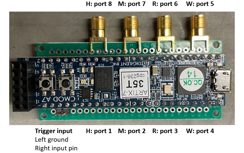
Before shipping, we have programmed the image to the Quad SPI’s flash memory on the board. Therefore, there is no need to program it using Vivado, it should be plug and play. The control FPGA code we provided contains 8 interfaces. By default, we are using ports 5 to 8. The sector index set can be configured through UART by MatLab command. The pa_ctl.m code is for the control FPGA configuration. Please refer to our reference MatLab code for the configuration detail. An example:
PA_atten = 10;   % Attenuation of the phased array, 1:15 larger attenuation, 0 means
pa_clk_count = 400; % Clock counter with 12 MHz clock speed, determine the interval between two beams
N_CB = 16;    % Size of the codebook
usrph.pa_arm_trigger(); % enable the gpio of USRP to send a trigger signal to the control FPGA
uartfh = serial('/dev/ttyUSB1','BaudRate', 115200); % Double check the serial port name
fopen(uartfh);
% pa_ctl(<beams to be scanned>, <attenuation>, <Control FPGA port>, <TX: 1, RX: 0>, <Clock counter>, <Serial port>)
pa_ctl(0:N_CB - 1, PA_atten, 5, 1, round(pa_clk_count), uartfh);
pa_ctl(0:N_CB - 1, PA_atten, 6, 1, round(pa_clk_count), uartfh);
pa_ctl(7ones(1,N_CB), PA_atten
pa_ctl(7ones(1,N_CB), PA_atten
fclose(uartfh);
System initiation
The system initiation needs to be done after the hardware connection. It will contain the following steps:
- Follow the steps in router configuration.
(Attention, double check the connection before turning on the wireless card or the ifconfig up command will return an error message and fail to initiate the phased array modules. Also, be careful not cut the connection after the interface is turned on or the NIC port might be burned.) - Run the configuration scripts on the host PC.
- Provide 5V DC power to the bridge boards. Connect the control FPGA to the host PC. (Note do not power up the control FPGA before you have setup the router or the router configuration will fail)
- Run the matlab control FPGA configuration command. (If beam sweeping does not needed, the script tx_mode.py, rx_mode.py, rf_status_tx.py and rf_status_tx.py can be used)
- Ready for communication.
Beam reconfiguration
The beam of the antenna array can be reconfigured by generating your own codebook. In this section, we will first describe how the codebook is loaded and used, followed by how to generate a customized codebook.
To achieve real-time beam sweeping, the beamforming configurations of the phased array cannot be loaded during the runtime since it will need a long time to send relatively large data to the phased array. Therefore, in common phased array design, the set of beamforming configurations which is called codebook is preloaded to the phased array. Then when the beam sweeping happens, only very small data containing beam index is needed which guarantees real-time beam reconfiguration.
For the Wi-Fi card we use, the codebook loading procedure first happens when runs ‘ifconfig wlan0 up’. The driver will load the codebook to the phased arrays based on the configuration in the ‘wil620_D0_0.brd’ file. But this procedure is not that robust after hardware reconfiguration happened in M-Cube design and also limits the flexibility of beam reconfiguration during runtime. Therefore, we provided ‘load_codebook.py’ which can make use of the WMI command ‘set_pattern’ to load a codebook to the phased array. By default, the script will read the codebook from file ’15beam.mat’ which contains a codebook sweeping the angle of the elevation, load them one by one using ‘set_pattern’ command and finally load a quasi-omni beam to the beam with index 15. Therefore, by default, the phased array is loaded with a hierarchical codebook. During the M-Cube initiation procedure, the ‘ldcb.sh’ script will call ‘load_codebook.py’ to load the hierarchical codebook to the enabled RF modules.
To reconfigure the beam, please first refer to the ‘beamgen_15.m’ which shows how to generate the ’15beam.mat’ file we provided. The code contains two procedures: i) generate an idea steering vector based on beamforming direction; ii) calibrate the hardware phase shift recorded in ‘steer_vector_calib.mat’ (we measured the phase shift from one phased array which theoretically may result in some offset for other phased arrays but it works reasonably well for all phased arrays based on some tests); iii) quantize the phase shift and generate the final codebook file. Please check the code for more details. After generating the codebook, please modify the ‘load_codebook.py’ to load the codebook as you want.
FAQ
- If we meet the ‘ifconfig: SIOCSIFFLAGS: Timer expired‘ issue persistently, what has happened?
A: First, please make sure all IF ports on the NIC are connected to one PM with the white coaxial cable. This error occurs during the initiation process of the NIC. The NIC will ping the PMs enabled in the brd file. If there is no response from the PM, the driver will give out this error. So when you see this error, please power down the router, double-check the cable connection and then start the configuration.
If you see this error persistently even though you checked the connection and even if you directly connect the phased array to the NIC, it is possible that the port of the NIC is broken due to ESD or cable disconnection during operation. Since the port to be enabled is broken, the initialization process fails and causes this issue.
To verify which port is burnt, you need to replace the brd file ‘/lib/firmware/wil6210_D0.brd’ (or ‘wil6210_D0_0.brd’ need to check this in dmesg'wil6210 0001:01:00.0 wlan0: wil_reset: Use firmware <wil6210_sparrow_plus.fw> + board <wil6210_D0.brd>') on the router with the ones in ‘/brd_file’ folder in scripts through scp command. The brd files are named by enabled module number, ‘wil6210_D0.brd_0’ means only module 0 is enabled.
After replacing the brd file, run ifconfig wlan0 up to see whether the error persist or not. If persist, the corresponding port is burnt. If not, it is fine. Then repeat the procedure with another RF module enabled. (Remember to ifconfig wlan0 down after ifconfig up success, or the driver will not try the new brd file.)
You may try to connect the bridge board with another port on the NIC. (The antenna model does not need any modification) Also, you may need to replace the brd file. - Unknown event response on the server on the router?
NOT_SUPPORTED_EVENTID detected!!event 0x1900 no response.
A: There are some reasons for this error:
i) You do not initialize the interface with ifconfig wlan0 up before running the server. Bringing the interface up should solve the issue.
ii) The firmware version is not correct. When you run the python server, it should report the firmware version which should be 6.2.0.40 which supports the testing commands with event 0x1900 we used to reconfigure the phased array. Please reach us if you do not have the correct firmware version.
iii) If this happens during running the rf_module_enable part of ‘ldcb.sh’, it is caused by a connection issue. Please check the hardware connection. - Any replacement of the sparrow+ router from Airfide?
A: The sparrow+ router is discontinued. We still have some in stock but ordering another set from us. We have verified that Microtik router wAP60Gx3 can be used as the replacement of sparrow+. Please check the following link to see how to reconfigure the router. M-Cube with Microtik Devices – The M-Cube (M3) Project
Citing M-Cube
Bibtex:
@inproceedings{MCube,
author = {Zhao, Renjie and Woodford, Timothy and Wei, Teng and Qian, Kun and Zhang, Xinyu},
title = {M-Cube: A Millimeter-Wave Massive MIMO Software Radio},
year = {2020},
isbn = {9781450370851},
publisher = {Association for Computing Machinery},
address = {New York, NY, USA},
url = {https://doi.org/10.1145/3372224.3380892},
doi = {10.1145/3372224.3380892},
booktitle = {Proceedings of the 26th Annual International Conference on Mobile Computing and Networking},
articleno = {15},
numpages = {14},
keywords = {testbed, experimental platform, 60 GHz, software radio, MIMO, millimeter-wave},
location = {London, United Kingdom},
series = {MobiCom '20}
}
ACM Reference Format:
Renjie Zhao, Timothy Woodford, Teng Wei, Kun Qian, and Xinyu Zhang. 2020. M-Cube: a millimeter-wave massive MIMO software radio. In Proceedings of the 26th Annual International Conference on Mobile Computing and Networking (MobiCom '20). Association for Computing Machinery, New York, NY, USA, Article 15, 1–14. DOI:https://doi.org/10.1145/3372224.3380892
Contact
PI: Xinyu Zhang (xyzhang@ucsd.edu)
Student: Renjie Zhao (r2zhao@ucsd.edu)
Acknowledgment
M3 is currently supported by the NSF CCRI program (grant number CNS-1925767). We also acknowledge the gracious equipment donations/loans from Samsung Research America and National Instruments.